How to Measure Thermal Conductivity of Materials?

Thermal conductivity testing measures how quickly heat moves through a material, turning an abstract property into a value engineers can use. The right method depends on the sample: a dense metal plate, an insulating panel, and a small polymer coupon behave differently during testing. A guarded hot plate can measure steady heat flow through flat specimens. Transient methods can suit smaller samples or faster comparisons. Each approach has limits.

How to measure thermal conductivity of materials is therefore a question of method, preparation, and conditions—not just instrument choice. Technicians should record sample dimensions, temperature, surface condition, and moisture content. A tiny air gap can change the reading. So can poor contact between the specimen and sensor. Small differences matter. Results also need calibration and a stated uncertainty, especially when values guide product design or quality control. Standards can help laboratories select consistent procedures, but no method removes every source of error.

Physicist Lord Kelvin captured the value of careful measurement: “When you can measure what you are speaking about, and express it in numbers, you know something about it.” His principle applies directly to thermal testing, though a number alone is not proof of accuracy. A dependable result needs traceable equipment, a suitable method, and clear reporting. A clean number can still mislead. This guide will explain common techniques, sample preparation, and result interpretation, while noting where assumptions deserve a second look.
How to Measure Thermal Conductivity of Materials?

Define Thermal Conductivity (k) in W·m⁻¹·K⁻¹

Thermal conductivity, written as k, describes how readily heat moves through a material. Its SI unit is watts per metre per kelvin: W·m⁻¹·K⁻¹. In practical terms, k relates heat flow to a temperature gradient and the material’s dimensions. For an ideal, one-dimensional slab, a one-kelvin temperature difference across one metre produces a heat flow of k watts through each square metre. Real samples rarely behave quite so neatly.

A common steady-state measurement places a sample between controlled hot and cold surfaces. The operator records heat flow, sample thickness, area, and the temperature difference across the sample. Fourier’s law links these values: heat flux equals k multiplied by the temperature gradient, with direction shown by a minus sign. Higher k means heat passes through more readily under the same conditions.

That distinction matters. A thin metal sheet may transfer heat quickly, while a thick piece of the same metal offers more resistance.

Contact gaps, edge losses, moisture, and uneven temperatures can distort results. I would check these carefully before trusting a reported value; even careful setups leave some uncertainty.

Choose ASTM C177, C518, or E1461 for the Material

Choose the method that matches the material’s structure and the property you need. ASTM C177 uses a guarded hot plate to measure steady-state heat flow through flat specimens. It suits insulation boards and other low-conductivity materials when careful edge control and stable temperatures are practical. ASTM C518 uses a heat-flow meter and is often faster for routine testing of flat, uniform samples. ASTM’s C177 and C518 standards describe these steady-state approaches; neither removes the need to control thickness, moisture, and contact between the specimen and plates.

For ceramics, metals, and other materials where rapid heating is useful, ASTM E1461 measures thermal diffusivity using a flash method. Its stated applicability covers diffusivities from 0.1 to 1,000 mm²/s (ASTM E1461-13(2022)). The result is not conductivity by itself. Calculate conductivity from diffusivity, density, and specific heat, so errors in those inputs matter.

Small disks. Clean surfaces. Consistent thickness.

Match the test to the question, not just the sample. A porous insulation coupon may call for C177 or C518; a thin ceramic disk may fit E1461 better. Record specimen dimensions, conditioning, temperature, and replicate variation with every result. ASTM methods provide procedures, but sample preparation still shapes the measurement.

One imperfect detail: real materials may be layered or anisotropic, while a test often reports a simplified value. State that limitation clearly.

Condition and Size Specimens to the Selected ASTM Method

The specimen must match the selected ASTM method, not just fit the test apparatus. Different methods set different requirements for dimensions, conditioning, and surface preparation. Check the current standard before cutting material; a small mismatch can affect the result.

Condition specimens at the temperature and humidity specified by the method. Allow enough time for the material to reach equilibrium, especially if it absorbs moisture. Keep samples clean and protected from drafts or direct heat. Small details matter. Measure thickness at several points with a suitable instrument, and record the readings rather than relying on a nominal value. Check that faces are flat and parallel where the method requires good contact with the test surfaces.

Prepare enough specimens for the method’s required measurements and note any visible defects, such as voids or chipped edges. If machining exposes fresh surfaces or changes moisture exposure, consider whether the samples need further conditioning. Record dimensions, conditioning time, and any deviations. This step can feel fussy, and deciding when a specimen is truly stable is not always straightforward. Follow the method’s stated criteria, and document uncertainty instead of quietly assuming it away.

Measure Steady-State Heat Flow with ASTM C177 or C518

How to Measure Thermal Conductivity of Materials?

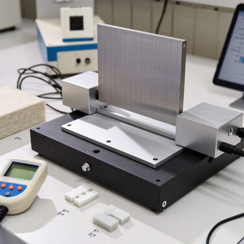
Steady-state testing measures how much heat passes through a specimen after temperatures stabilize. ASTM C177 uses a guarded hot plate, while ASTM C518 uses a calibrated heat flow meter. Both methods require careful control of temperature and specimen thickness. Small setup errors can shift the result.

For a reliable test, prepare flat specimens with measured thickness and clean, even surfaces. Place the sample between controlled hot and cold plates, then allow readings to settle. Record heat flow, temperature difference, thickness, and conditioning details. C177 can provide a direct measurement under specified conditions; C518 compares heat flow against reference materials. Results depend on the material, temperature range, moisture, and contact between surfaces. Equilibrium takes time. A draft or uneven sample can matter more than expected.

Tips: Check calibration and inspect the specimen for gaps or warping. Keep test conditions consistent, and repeat measurements when results vary. Note any imperfect contact rather than hiding it; that detail may help explain an unexpected value.

How to Measure Thermal Conductivity of Materials? - Measure Steady-State Heat Flow with ASTM C177 or C518

Representative example measurements for insulation specimens near a 25 °C mean temperature. Values are illustrative, not certified test results; actual results depend on specimen composition, density, moisture, thickness, temperature, and test conditions.

Specimen Thickness (m) Mean Temperature (°C) Hot-Side Temperature (°C) Cold-Side Temperature (°C) Metered Area (m²) Steady-State Heat Flow (W) Calculated Thermal Conductivity, k (W/m·K) Suitable Test Approach
Expanded polystyrene (EPS) board 0.050 25 35 15 0.090 1.26 0.035 ASTM C518 heat flow meter or ASTM C177 guarded hot plate
Extruded polystyrene (XPS) board 0.050 25 35 15 0.090 1.08 0.030 ASTM C518 heat flow meter or ASTM C177 guarded hot plate
Glass fiber insulation board 0.050 25 35 15 0.090 1.44 0.040 ASTM C518 heat flow meter or ASTM C177 guarded hot plate
Mineral wool insulation board 0.050 25 35 15 0.090 1.44 0.040 ASTM C518 heat flow meter or ASTM C177 guarded hot plate
Polyisocyanurate (polyiso) insulation board 0.050 25 35 15 0.090 0.90 0.025 ASTM C518 heat flow meter or ASTM C177 guarded hot plate
Calculation: k = Q × L ÷ (A × ΔT), where Q is steady-state heat flow, L is specimen thickness, A is metered area, and ΔT is the temperature difference across the specimen. ASTM C177 uses the guarded-hot-plate method; ASTM C518 uses the heat-flow-meter method. Follow the applicable standard for specimen preparation, calibration, conditioning, and reporting.

Calculate k = α·ρ·Cp from ASTM E1461 Diffusivity Data

ASTM E1461 uses a flash technique to determine thermal diffusivity, α. A short energy pulse heats one face of a specimen, while a detector records the temperature rise on the opposite face. The result describes how quickly heat spreads; it is not thermal conductivity by itself. To calculate conductivity, use k = α·ρ·Cp, where ρ is density and Cp is specific heat capacity. Keep units consistent, and use values measured or established for the same temperature range.

For example, α = 0.8 mm²/s, ρ = 2,500 kg/m³, and Cp = 800 J/(kg·K) give k ≈ 1.6 W/(m·K), after converting α to m²/s.

Check the specimen’s dimensions and density carefully; pores or uneven composition can shift the result. That matters. Surface condition, pulse duration, and temperature measurement can also affect diffusivity. I would not treat a calculated value as exact just because the arithmetic is simple. Record the test temperature, sample preparation, and source of Cp alongside the result, so another reader can judge whether the comparison is fair.

Request a Quote

For more information on our instruments, consumables, or services, or to request a quote, complete the contact form below, and one of our associates will reach out to you!

Request a Service Quote

To request service on your machine(s), complete the contact form below, and one of our associates will reach out to you!

Browse by:

  • Test Property
  • Manufacturer