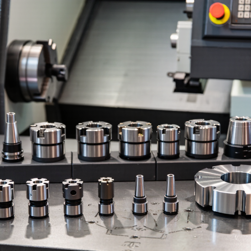
Top 10 Turning Tool Holder Types for Buyers
Choosing a Turning Tool Holder is not a catalog exercise. It is a decision about rigidity, clearance, insert geometry, and the workpiece material. A holder that looks suitable on a product page may vibrate when a long bar reaches deep inside a bore. A poor fit can also leave chatter marks, waste inserts, and slow a repeat job. Small details matter.
This guide compares ten common holder types, from external turning holders to boring bars and specialized grooving designs. It explains where each one fits, what to check before buying, and which trade-offs deserve attention. Shank size, clamping method, approach angle, and machine compatibility all affect the result. So does the actual setup. A rigid holder cannot rescue an unstable workpiece.
The line below is an original editorial maxim, voiced by fictional shop-floor expert Maya Chen; it is not a sourced quotation: “Choose the holder for the cut you run, not the label on the box.” That distinction is easy to overlook. Buyers should verify dimensions against the machine manual and confirm insert compatibility with the supplier. This overview offers a practical starting point, not a substitute for testing. A short trial cut can reveal what a specification sheet cannot: how the holder behaves under real cutting conditions.
How Turning Tool Holders Secure and Position Cutting Tools
A turning tool holder does more than clamp an insert. It controls the insert’s height, angle, and distance from the spindle, while resisting cutting forces. A rigid clamp limits movement; a short, well-supported overhang helps reduce deflection. Small alignment errors matter. They can leave uneven wear, chatter marks, or a poor surface finish. A holder may look secure and still flex under load.
For a measurable setup, check insert seating, clamp contact, and tool-tip height before cutting. ISO 230-2:2014 sets out methods for measuring machine-tool positioning accuracy and repeatability; these checks help separate machine-axis error from holder setup issues. ISO 13399 provides a standardized framework for representing cutting-tool data, supporting consistent tool identification and setup records. Neither standard guarantees a good cut. Actual performance still depends on workpiece material, cutting forces, and holder condition. A dial indicator can reveal runout, but the reading alone does not explain its cause. That part takes judgment. Remove chips from the pocket, inspect the seating faces, and retest after tightening. A clean-looking setup is not always a correct one.
Ten Common Turning Tool Holder Types and Their Applications
Right-hand holders feed toward the chuck on many standard lathe setups, while left-hand holders feed away from it. Check the machine’s orientation before choosing. Small detail, big difference. Neutral holders can approach shoulders and perform facing cuts without a pronounced cutting direction. Straight holders suit open external surfaces; offset holders can reach near shoulders, though they need adequate clearance.
Face-turning holders are designed to cut across a workpiece’s end. Boring-bar holders carry tools inside a drilled opening, where bar overhang and rigidity affect chatter. Threading holders use a pointed insert to form a specified thread profile. Grooving holders cut narrow channels, such as relief grooves, while parting-off holders separate a finished component from stock. Keep the tool aligned with the work and check the insert geometry against the job.
These types overlap in real shops: one holder style may perform more than one operation with the right insert and setup. Still, matching the holder to the cut often improves access and chip control. A slim boring bar may fit the hole, yet flex under heavy cutting. That trade-off is easy to underestimate. Consider material, tool reach, machine rigidity, and the workpiece drawing before settling on a holder.
Top 10 Turning Tool Holder Types and Their Applications
This chart compares common holder-and-insert combinations by the typical number of usable cutting edges on the insert. Edge count depends on insert geometry; the applications below are general examples, and the right choice depends on the workpiece, cut, and setup.
| Holder and Insert | Common Applications |
|---|---|
| PCLNR / CNMG | General external turning and roughing |
| PDJNR / DNMG | External turning, profiling, and finishing |
| SVJBR / VBMT | Profiling and turning contoured surfaces |
| PTGNR / TNMG | General turning and medium-duty cutting |
| PSKNR / SNMG | Heavy-duty external turning and roughing |
| PWLNR / WNMG | Roughing and turning where a robust cutting edge is useful |
| SCLCR / CCMT | Light turning, finishing, and some boring setups |
| SDJCR / DCMT | Profiling, finishing, and internal turning setups |
| SVJBR / VBMT | Detail profiling and finishing contoured features |
| STGCR / TCMT | Light turning and boring applications |
Typical edge counts shown: CNMG and SNMG 8; DNMG, VBMT, TNMG, and WNMG 6; CCMT and DCMT 2; TCMT 3. Actual usable edges vary with insert design and cutting conditions.
Key Holder Features: Shanks, Clamping Systems, and Insert Seats
A turning holder’s shank is the first fit to check. Match its height and width to the turret or tool post, then verify the overhang. A long, thin shank can flex under cutting pressure; the finish may show chatter marks. ISO 5608:2021 standardizes designation and dimensions for turning and boring holders, giving buyers a consistent reference for comparing interfaces. Clamping matters too. A top clamp is simple to inspect, while a lever-style system can make insert changes quicker. Neither compensates for a dirty or damaged seat.
Insert seats determine how securely the cutting edge meets the workpiece. ISO 1832:2017 standardizes insert designation, including characteristics such as shape, clearance angle, and tolerance class. Check that the holder’s seat matches the insert code and intended cutting direction. A small mismatch can cause rocking or uneven edge wear. I would still verify fit on the actual machine; catalog dimensions do not reveal every clearance issue.
Tips: Wipe the seat before fitting an insert. Check that the clamp contacts the insert firmly, without forcing it. For a first trial, note the overhang, cutting sound, and wear pattern. They can expose a poor setup faster than a spec sheet.
How to Match a Tool Holder to the Machine and Turning Operation
Matching a turning tool holder starts with the machine interface. Shank size, turret style, clamping method, and center height must all agree. Even a small mismatch can shift the insert off center or reduce clamping stability. For external turning, a rigid holder often suits straight cuts; check clearance near the chuck and workpiece shoulder. Grooving and parting need a blade held firmly, with enough reach to clear the workpiece face. Boring bars must fit the bore and stay as short as practical. Long overhang invites vibration.
Then match the holder to the operation and insert geometry. Threading needs a holder aligned with the thread direction, while profiling may require extra flank clearance. Consider workpiece material, cut depth, feed, coolant access, and the turret’s available stations. On a compact lathe, a bulky holder may collide with a tailstock or neighboring tool. Check the machine manual and measure the actual setup, not just the catalog drawing. A dry run at safe clearance can reveal interference before cutting. There is rarely one perfect choice. I still recheck overhang; it is easy to underestimate.
Buyer Checks for Compatibility, Rigidity, and Service Life
A turning tool holder is only useful when it matches the machine, insert, and operation. Check the shank dimensions against the turret or tool post, then confirm the insert shape and clamping method. External turning, facing, threading, grooving, and parting holders serve different cuts; boring bars also need enough clearance inside the workpiece. Small mismatches matter. A holder that seats unevenly can shift under load.
Rigidity depends on more than the holder’s material. Keep overhang short, make sure the clamping surfaces are clean, and choose a suitable bar diameter for internal work. Watch for vibration on the first test cut: chatter marks on the part can signal excess deflection. For service life, inspect the clamp, pocket, and cutting edge during routine changes. Coolant access and chip flow affect heat and wear, though the ideal setup varies with material and cutting conditions. A catalog fit can still disappoint.
Tips: Compare drawings, not just product names. Test one holder at the intended cutting depth, then record finish, vibration, and insert wear. If results are inconsistent, recheck alignment before blaming the tool.
| No. | Holder type | Typical use | Compatibility checks | Rigidity considerations | Service-life considerations |
|---|---|---|---|---|---|
| 1 | External negative-insert holder with top or lever clamping | General-purpose external turning, facing, and heavier cuts where a robust insert is suitable. | Match the insert shape, size, thickness, nose radius, and hand to the holder designation. Confirm the clamping system and that the turret accepts the shank size. | A firm insert seat and secure clamp support stable cutting. Check clearance around the workpiece, chuck, and turret before selecting the holder hand and approach angle. | Keep the insert seat and clamp clean and undamaged. Index or replace inserts when cutting edges wear, chip, or no longer meet the required finish. |
| 2 | External positive-insert holder with screw clamping | Finishing and lighter cuts, including applications where lower cutting forces are useful. | Confirm the positive insert’s shape, size, thickness, screw-hole arrangement, and orientation match the holder. Use the specified clamping screw and seating parts. | Positive geometry can reduce cutting forces, but the insert and clamp must be fully seated. Avoid excessive tool projection, especially on small or less rigid setups. | Inspect the screw, insert pocket, and cutting edge regularly. Replace damaged screws or seats; do not compensate for a loose fit by overtightening. |
| 3 | Steel-shank boring bar | Internal turning and boring in holes with adequate room for the bar and chip flow. | Check bar diameter against the minimum bore, and confirm the insert code, hand, clamping method, and required boring depth. | Keep overhang as short as the job allows and clamp the bar securely. Steel bars are commonly selected for shorter overhangs; vibration risk rises as unsupported length increases. | Use cutting conditions appropriate to the bar’s reach and material. Check the bar for wear, damage, and built-up material, and maintain a sharp, correctly seated insert. |
| 4 | Carbide-shank boring bar | Internal turning where a longer overhang or greater resistance to deflection than a comparable steel bar is needed. | Verify bar diameter, minimum bore, insert and screw specifications, machine clamping method, and clearance throughout the bore. | Carbide is stiffer than steel of the same dimensions but is less tolerant of impact and mishandling. Use a secure clamp and avoid sudden shocks or interrupted cuts beyond the bar’s capability. | Prevent chipping from impact, poor alignment, or unstable cutting. Inspect the bar and insert seat for cracks or damage and follow the tool maker’s handling guidance. |
| 5 | External grooving and parting blade holder | Cutting grooves or separating parts from bar stock. | Match blade width, height, length, insert system, and holder pocket. Check required groove width, cut depth, machine clearance, and workpiece diameter. | Set the blade at the correct center height and square to the workpiece. Minimize blade projection and ensure the workpiece and setup are well supported. | Maintain a clear chip path and use suitable coolant where applicable. Replace chipped inserts and inspect blade pockets and clamping surfaces for wear. |
| 6 | Internal grooving holder or grooving bar | Making grooves, reliefs, or recesses inside a bore. | Check the bar diameter against the bore, along with groove width, required depth, insert width, and the holder’s minimum-bore limits. | Use the largest bar that fits with adequate clearance and keep its overhang short. Confirm that the holder will not contact the bore wall during entry or withdrawal. | Control chip evacuation to reduce recutting and edge damage. Inspect the insert, pocket, and bar for wear, especially after deep or narrow grooving operations. |
| 7 | External threading holder | Cutting external threads with a single-point threading insert. | Match the insert profile and pitch range to the thread standard and required form. Confirm insert hand, holder hand, seat orientation, and clearance at the shoulder. | Seat the insert securely and align it correctly to the work axis. A rigid setup helps reduce chatter and maintain thread-form consistency over repeated passes. | Use an edge and cutting setup suited to the work material. Check the cutting edge and insert alignment if the thread finish or profile begins to deteriorate. |
| 8 | Internal threading bar | Cutting threads inside a bore where a single-point threading tool can reach the feature. | Verify the bar fits the minimum bore and reaches the thread length. Match insert profile and pitch to the thread, and check the required hand and internal clearance. | Minimize overhang and ensure the bar is firmly clamped. Confirm there is room for chip evacuation and for safe entry and exit from the thread. | Monitor insert-edge wear and chip control. A damaged edge or unstable bar can affect thread form and surface finish; inspect the bar and insert seat between jobs. |
| 9 | Profiling and copy-turning holder | Contouring shoulders, radii, tapers, and other shaped external or internal features. | Check insert shape, nose radius, cutting direction, and clearance against the workpiece profile. Confirm the insert can reach the full contour without holder interference. | Choose a holder and insert orientation that provide clearance without excessive overhang. Complex contours may require checking for interference along the complete tool path. | Use a suitable insert geometry for the material and contour. Inspect the edge when the profile finish changes, and avoid allowing the holder or insert to rub on the finished surface. |
| 10 | Modular-interface turning holder | Applications requiring interchangeable heads or repeatable tool setup across compatible machine interfaces. | Confirm the interface standard, size, locking method, holder orientation, and machine-side connection all match. Also verify insert compatibility at the cutting head. | Clean mating faces before assembly and tighten the connection as specified. Interface condition and secure locking are essential to repeatability and cutting stability. | Protect locating faces and locking features from chips, corrosion, and impact. Inspect mating surfaces and locking components regularly, and replace worn parts as needed. |
Article Source:
Have Questions? We're Here to Help!
Give us a call at (864) 989-0566 or send us a message to discuss our testing equipment with an expert.