What Is a Control Relay and How Does It Work?
A Control Relay is a small switching device with an outsized role: it lets a low-power signal control a separate electrical circuit. Inside, a coil creates a magnetic field when energized. That field moves an armature, opening or closing contacts that may operate a motor starter, alarm, or lighting circuit. In a control cabinet, the action can be heard as a brief click. The sound is reassuring, but it does not prove the contacts are healthy.
The U.S. Department of Energy’s 2021 U.S. Industrial and Commercial Motor System Market Assessment Report estimates that motor-driven systems use about 68% of U.S. industrial electricity. That figure does not measure relay use. It does show why dependable control and switching equipment matters around industrial motors. Tony R. Kuphaldt, an electrical engineering educator and author of Lessons in Electric Circuits, describes the basic device plainly: “A relay is an electrically operated switch.” That definition is useful. It is not the whole story.
A relay’s coil voltage, contact rating, switching load, and operating environment all affect safe, reliable performance. A relay rated for a resistive load may not suit a motor’s starting current. Heat, dust, vibration, and worn contacts can also cause trouble. The practical lesson is simple: choose from the circuit requirements, not the relay’s appearance. Even a clear wiring diagram can hide an assumption worth checking. This introduction explains how relays work, where they are used, and what to inspect before selecting one.
What a Control Relay Is and What It Does
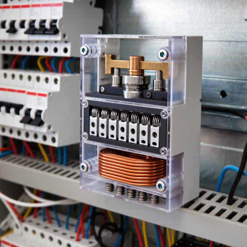
A control relay is an electrically operated switch used to let one circuit control another. A low-power signal energizes a coil inside the relay. The magnetic field pulls a small armature, which changes the position of the contacts. Click. That sound is often heard in control panels, though quiet relays may not make it.
Many relays provide normally open and normally closed contacts. A normally open contact closes when the coil is energized; a normally closed contact opens. This lets a thermostat, sensor, or controller switch a pump, warning lamp, or other load without carrying that load’s current through its own output. The relay’s coil voltage and contact ratings must match the circuit. Check both.
In a cabinet, the relay may sit on a socket beside labeled wires, making faults easier to trace or replace. Its separation between coil and contacts can help keep control and load circuits distinct, but it should not automatically be treated as certified safety isolation. Contact wear, heat, and switching surges matter too. A relay can seem like a simple part, yet choosing one by appearance alone is an easy mistake.
Control Relay Operation: Coil and Normally Open Contact
A control relay uses an energized coil to move its contacts. This illustrative waveform shows a 24 V DC coil energized at 0 ms and switched off at 60 ms. The normally open contact closes after a representative 15 ms pickup time and opens after a representative 10 ms release time. Actual timing varies by relay and operating conditions.
Main Components and Their Functions
A control relay contains a coil, a movable armature, a spring, and electrical contacts. When control voltage reaches the coil, its magnetic field pulls the armature inward. The movement opens or closes the contacts, switching a separate circuit. No moving parts are silent forever; a faint click is normal.
The contacts carry the switched current, while terminals connect the relay to control and load wiring. Some relays have normally open contacts, which close when the coil is energized. Normally closed contacts open instead. A spring returns the armature when power stops, restoring the contacts to their resting position. The insulating housing helps protect internal parts from dust and accidental contact, but it does not make every relay suitable for every environment. Check the coil voltage and contact ratings against the equipment specifications.
Tips: Match the relay’s coil voltage to the control supply, and never exceed its contact rating. If operation seems inconsistent, inspect terminal tightness and look for heat discoloration. Ratings matter. A relay can click correctly and still have worn contacts.
How a Control Relay Operates Step by Step
A control relay lets a low-power signal switch a separate electrical circuit. The process starts when a control voltage reaches the relay coil. In a panel, this might happen after a sensor detects a warm pipe or an operator presses a button. The coil draws current and creates a magnetic field.
Then the magnetic field pulls a small metal armature toward the coil. You may hear a soft click. That movement changes the contact positions: normally open contacts close, while normally closed contacts open. The contacts can then complete or interrupt a circuit powering a lamp, valve, or motor starter. The control circuit and switched circuit are electrically separate, though their isolation depends on the relay’s design and condition.
When the control voltage stops, the magnetic field collapses. A spring usually returns the armature, restoring the contacts to their resting positions. The cycle can repeat many times, but contacts wear, and coils can overheat if used outside their ratings. Check the relay’s coil voltage and contact rating against the actual circuit, not just its appearance. A click alone is not proof that the contacts are working; measuring continuity under safe, de-energized conditions can reveal a fault. Real installations vary, and that detail is easy to overlook.
What Is a Control Relay and How Does It Work? - How a Control Relay Operates Step by Step
Where Control Relays Are Used
Control relays are common in equipment that needs one signal to operate another circuit. In a building’s HVAC panel, a thermostat may energize a relay coil, which then switches a fan or pump. The control wiring carries the command; the relay contacts handle the connected load within their rated limits. They switch loads. That separation can make control circuits easier to organize and troubleshoot.
You will also find control relays in industrial control cabinets, where they operate indicator lights, small motors, valves, and machine sequences. In a water system, for example, a level sensor can trigger a relay when a tank needs filling. Lighting panels and access-control equipment use relays to switch circuits in response to timers, sensors, or buttons.
Not every relay suits every load. Motor start-up current, coil voltage, contact ratings, and switching frequency all matter.
In practice, panel wiring can become crowded, so clear labels and a readable wiring diagram save time during maintenance. A relay may also need suitable protection against voltage spikes from an inductive load.
Check the equipment specifications before choosing one.