What Is a Brushless Motor and How Does It Work?

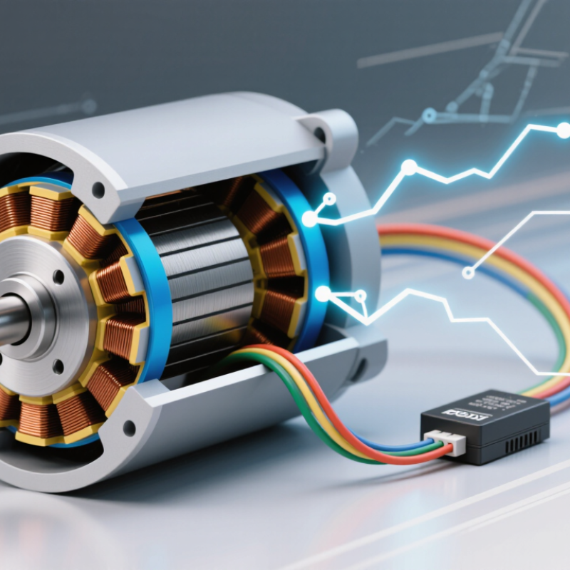
A brushless motor can look almost ordinary from the outside: a compact metal case, a shaft, and wires leading to an electronic controller. Inside, permanent magnets rotate around or within windings, while the controller switches current through those windings in a timed sequence. There are no brushes rubbing against a commutator. Less friction. Less routine wear.

Austin Hughes, co-author of Electric Motors and Drives, explains motor-drive principles that include electronic commutation. A concise paraphrase of the key idea is: “Electronic switching replaces the mechanical commutation performed by brushes.” This is a paraphrase, not a direct quotation. It points to the defining difference—and to why controller design matters as much as the motor itself.

Understanding how a brushless motor works means following the sequence: a sensor or controller estimates rotor position, current energizes selected coils, and magnetic forces turn the shaft. The process repeats rapidly. In a small drone, that sequence helps deliver quick changes in speed; in a workshop fan, it can support quiet, steady rotation. Performance still depends on the motor, controller, load, and cooling working together. A high efficiency figure alone tells only part of the story. The details can be less tidy than a simple diagram suggests, especially when sensorless control must infer rotor position at low speeds. This guide explains the main parts, the switching process, and the practical trade-offs behind the technology.
What Is a Brushless Motor and How Does It Work?

What Defines a Brushless Motor?

A brushless motor has no carbon brushes rubbing against a commutator to deliver current to its rotating part. That missing contact is its defining feature. Coils sit in the stationary section, called the stator, while permanent magnets are commonly attached to the rotor. The controller switches current through the coils in a timed sequence, creating a magnetic field that pulls the rotor around. That is the basic idea.

The timing matters. Sensors may report the rotor’s position, or the controller may estimate it from electrical signals. With that information, it energizes the right coils as the rotor turns. Picture a small fan starting quietly on a desk: its controller adjusts the magnetic push rather than relying on sliding contacts. The exact design varies, so not every brushless motor starts or responds in the same way.

Removing brushes reduces friction and wear at that contact point, and it avoids brush-generated electrical sparking. It does not make the motor maintenance-free. Bearings can still wear, and heat can damage insulation or magnets. The electronic controller also adds complexity and needs suitable settings. “Brushless” sounds like a complete description, but it leaves out important details, including motor construction, cooling, and control quality.

What Is a Brushless Motor and How Does It Work?

What Defines a Brushless Motor?

A brushless motor has no mechanical brushes or commutator. Instead, an electronic controller switches current through the motor’s phases in coordination with rotor position. These idealized, normalized three-phase waveforms illustrate how the phases are electrically offset; actual motor waveforms vary by design.

The Main Components of a Brushless Motor

What Is a Brushless Motor and How Does It Work?
The Main Components of a Brushless Motor

A brushless motor has a stationary stator, a rotating rotor, and an electronic controller. The stator’s laminated steel core carries copper windings. When current flows through them, they create a rotating magnetic field. The rotor’s permanent magnets follow that field, turning the shaft without brushes rubbing against a commutator. Small detail, big consequence: less brush wear, but more reliance on electronics.

The controller switches current between the windings to keep the rotor moving. It may use Hall-effect sensors to track rotor position, or estimate position from voltage signals. Sensorless designs can reduce parts, though low-speed control may be less straightforward. Bearings support the shaft; the housing holds components in alignment and helps manage heat. In practice, a warm casing can signal a cooling or load issue, but temperature alone does not diagnose the cause.

The International Energy Agency’s 2016 report, Energy Efficiency Policy Opportunities for Electric Motor-Driven Systems, estimates that motor-driven systems use about 45% of global electricity. That figure covers many motor types, not brushless motors alone. It does underline why component choices matter: winding design, magnets, control electronics, and cooling all affect performance. A motor is not efficient just because it is brushless. The application and operating conditions matter, too.

How a Brushless Motor Produces Rotation

A brushless motor produces rotation by switching current through stationary coils in a timed sequence. These coils form the stator’s magnetic field. Permanent magnets on the rotor respond to that moving field, creating torque and turning the shaft. The rotor keeps following as the controller advances the energized coils around the stator.

Timing matters. Hall sensors can report the rotor’s position; sensorless designs infer it from voltage generated in the coils. The controller then switches current between phases, a process called electronic commutation. Change the sequence, and the rotor can turn the other way. Adjust current, and the motor’s torque and speed change. Real systems are less tidy: friction, heat, and changing loads affect performance, while sensorless motors can struggle to start smoothly.

The U.S. Department of Energy’s 2002 United States Industrial Electric Motor Systems Market Opportunities Assessment estimated that motors used 68% of industrial electricity. That figure covers industrial motors broadly, not brushless motors alone, but it shows why efficient control matters. A useful mental picture is a magnetic field pulling the rotor around like an invisible hand. It is only a simplification: the controller must continuously coordinate current and rotor position for steady rotation.

How Electronic Commutation Controls the Motor

A brushless motor replaces physical brushes with electronic commutation. A controller switches current through the motor’s windings in a timed sequence. This creates a moving magnetic field that pulls the rotor around. No brush contact. Less friction, but more control is needed.

The controller must estimate or detect the rotor’s position before choosing which windings to energize. Hall sensors can report position directly; sensorless designs often read voltage generated by the spinning motor. At very low speeds, that signal can be weak, making startup control more challenging. The controller’s transistors then switch current between phases, much like turning tiny electrical gates on and off. Their timing affects torque, heat, noise, and efficiency. A mistimed switch can make rotation feel rough or waste energy. In practice, these effects depend on motor design and load, so one setting rarely suits every application. The part I’d watch most closely is low-speed behavior: a motor may sound smooth at steady speed yet hesitate under a heavy load.

What Is a Brushless Motor and How Does It Work? - How Electronic Commutation Controls the Motor

Aspect How It Works Typical Details
Basic definition A brushless DC motor (BLDC) produces rotation by switching current electronically through its stator windings. Unlike a brushed motor, it does not use brushes and a mechanical commutator to switch rotor current. The electronic controller performs commutation, coordinating the stator’s magnetic field with the rotor’s position.
Main components The rotor carries permanent magnets, while the stator contains energized windings. A motor controller uses power switches and control circuitry to drive those windings. Common three-phase motors have three stator phase connections, often labeled A, B, and C. The rotor may have multiple magnetic poles.
Electronic commutation The controller changes which stator phases carry current and the direction of that current. This creates a rotating magnetic field that pulls the rotor around. In six-step control, two phases are driven at a time while the third phase is left undriven during each commutation state.
Example six-step sequence 1. A positive, B negative, C floating
2. A positive, C negative, B floating
3. B positive, C negative, A floating
4. B positive, A negative, C floating
5. C positive, A negative, B floating
6. C positive, B negative, A floating
“Positive” and “negative” indicate the direction of phase current for that state. The controller repeats the sequence, advancing to the next state as the rotor turns.
Rotor-position information The controller needs to determine when to change the energized phases. It can use position sensors or estimate rotor position from the motor’s electrical behavior. Hall-effect sensors are a common sensor-based method. Sensorless control often uses back electromotive force (back EMF) or other electrical measurements.
Back EMF As the rotor magnets move past the stator windings, they induce voltage in the windings. This generated voltage is called back EMF and varies with rotor motion. In some sensorless six-step drives, the controller monitors the undriven phase’s back-EMF zero crossing to help time commutation.
Speed and torque control The controller adjusts the electrical input to regulate motor operation. Pulse-width modulation (PWM) rapidly switches power on and off to control the effective voltage applied to the windings. Changing PWM duty cycle can change the motor’s average applied voltage. Actual speed and torque also depend on the motor, load, supply, and control strategy.
Starting and low-speed operation At standstill, a sensorless controller cannot rely on rotation-induced back EMF because it is absent or very small. It must use another starting method or position information. Possible approaches include Hall sensors, rotor-position estimation, or a controlled open-loop startup sequence before sensorless operation takes over.
Common control methods Six-step (trapezoidal) control switches phases in discrete states. Field-oriented control (FOC) regulates the motor’s magnetic-field and torque-producing current components. Six-step control is relatively straightforward. FOC can provide smoother torque and quieter operation when properly implemented.
Practical characteristics Removing brushes avoids brush wear and mechanical brush sparking. However, the motor requires an electronic controller, and performance depends on the motor-controller combination. Thermal limits, winding resistance, magnetic design, switching frequency, load, and control settings all affect efficiency and operating range.
Note: Commutation sequences, sensing methods, and control behavior vary with motor design and controller implementation. The six-step sequence shown is an illustrative phase-order example.

Common Types and Applications of Brushless Motors

Brushless motors replace mechanical brushes with electronic switching, reducing contact wear and sparking. Their common types include brushless DC motors (BLDC), permanent-magnet synchronous motors (PMSM), and induction motors. BLDC designs often use trapezoidal control; PMSMs typically deliver smoother torque through sinusoidal control. These categories can overlap in commercial terminology, so check the motor’s control method and specifications.

Applications range from quiet ceiling fans and water pumps to factory conveyors, robotics, and electric vehicles. The International Energy Agency’s Global EV Outlook 2024 reports nearly 14 million electric-car sales in 2023, around 18% of global car sales. Many electric drivetrains use brushless traction motors, where precise speed control and high power density matter. Induction motors avoid permanent magnets, but their operating losses and controller requirements differ. Small details matter.

Tip: Match the motor to its load, speed range, and cooling conditions. For a pump, compare efficiency at its usual operating point—not only the rated maximum. A motor may look efficient on paper yet run hot in a cramped enclosure.

Article Source:

Request a Quote

For more information on our instruments, consumables, or services, or to request a quote, complete the contact form below, and one of our associates will reach out to you!

Request a Service Quote

To request service on your machine(s), complete the contact form below, and one of our associates will reach out to you!

Browse by:

  • Test Property
  • Manufacturer