What Is an Arm Cylinder and How Does It Work?
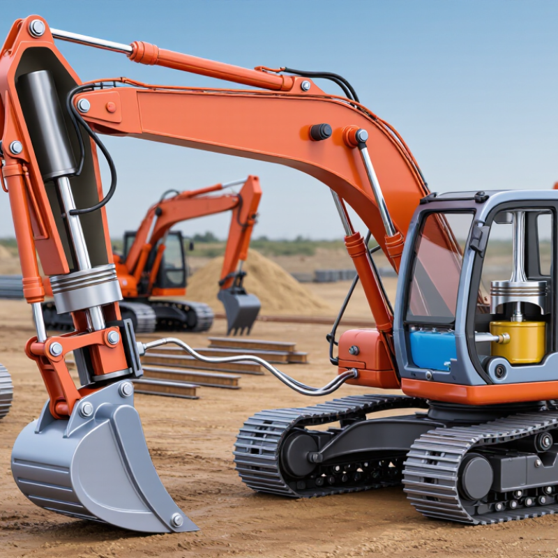
An Arm Cylinder is a hydraulic actuator that moves an excavator’s arm, often called the dipper or stick. It converts pressurized fluid into controlled linear force. Inside its steel barrel, hydraulic oil pushes a piston. The piston rod then extends or retracts, changing the arm’s position. Simple in principle. Demanding in practice.
On a tracked excavator, the Arm Cylinder works with the boom and bucket cylinders. The operator moves a control valve, which directs oil through hoses and ports. Pressure acts on one side of the piston, while return oil leaves the opposite chamber. Flow rate influences speed. Pressure influences force. Load, geometry, friction, and temperature influence real performance.
Industry research confirms the cylinder’s wider importance. Grand View Research identifies construction equipment as a major application area for hydraulic cylinders. Its market analysis also links demand with infrastructure development and material-handling equipment. ISO 4413 provides principles for hydraulic-system safety, including pressure control, hose routing, and energy isolation. These references show that cylinder design involves more than visible lifting power.
A practical inspection may reveal a damp rod, uneven movement, or a faint knocking sound. Such symptoms can indicate seal wear, trapped air, contamination, or misalignment. A clean cylinder is not always a healthy cylinder. Internal bypassing may reduce force without creating an obvious external leak. This guide explains the Arm Cylinder’s components, operating cycle, force behavior, and maintenance concerns. It also acknowledges a common limitation: field conditions rarely match laboratory assumptions. Manufacturer specifications and trained inspection remain essential.
Arm Cylinder Definition: A Hydraulic Actuator Rated Around 25–35 MPa
An arm cylinder is a hydraulic actuator that moves an excavator’s arm through controlled extension and retraction. It commonly operates within a working pressure range of about 25–35 MPa. The exact rating depends on cylinder design, machine settings, and safety margins. Hydraulic oil enters one side of the barrel and pushes the piston. Oil leaving the opposite chamber returns through the control valve. This creates smooth movement, even under heavy digging loads. The piston rod transfers force to the arm linkage, while seals prevent oil leakage and dirt entry.
Tips: Check the pressure rating before replacement. Inspect the rod for scratches, bending, or rust. A small leak can become serious. Clean fittings before connecting hoses. During field service, I have seen loose connections imitate internal cylinder failure. Pressure testing often reveals the real problem.
Good performance also depends on oil cleanliness and correct alignment. Side loading can damage bushings, seals, and the rod surface. Never judge a cylinder only by its outside appearance. A polished rod may still hide internal scoring. Pressure should be measured with suitable equipment, not guessed from slow movement. The 25–35 MPa range describes a common operating class, not a universal specification. Temperature changes can also affect oil viscosity and response speed. In practice, maintenance records are sometimes incomplete, so technicians must verify measurements carefully before making repairs.
Force Conversion: Hydraulic Force F = P × A Drives Arm Movement
An arm cylinder converts hydraulic pressure into controlled mechanical force. Its governing equation is F = P × A, where F is force, P is fluid pressure, and A is piston area. For example, a 100-millimeter bore has an area of about 7,854 square millimeters. At 25 MPa, it can produce approximately 196 kilonewtons of theoretical extension force. That is enough to lift a heavy arm, but only under ideal conditions.
Real machines are less perfect. Seal friction, oil temperature, leakage, and flow restrictions reduce usable force. During retraction, the rod occupies part of the piston area, so pulling force is lower than pushing force. Movement speed depends on flow rate, not pressure alone. More flow fills the cylinder faster, while higher pressure mainly increases available force. ISO 4413 emphasizes pressure control, contamination management, and safe energy isolation in hydraulic systems. These details matter beside a real excavator, where a small pressure fluctuation can change bucket movement noticeably. A 2024 Grand View Research analysis estimated the global hydraulic-cylinder market at more than 15 billion dollars, reflecting broad demand across construction, agriculture, and industrial equipment. Market size does not guarantee reliability. Field technicians still inspect rod surfaces, fittings, and fluid condition before trusting a force calculation. The equation is simple. The application is not.
Work Cycle: Pump Flow, Valve Spool, Extension, Retraction, and Load
What Is an Arm Cylinder and How Does It Work?
An arm cylinder is a hydraulic actuator that moves an excavator’s arm with controlled force. Its steel barrel contains a piston, rod, seals, and hydraulic oil. The work cycle begins at the pump. The pump sends pressurized oil through hoses toward the control valve. Good filtration matters because tiny particles can damage seals and score polished surfaces.
When the operator moves the control lever, the valve spool shifts inside its housing. That spool directs flow to one side of the piston. Oil entering the cap end pushes the piston outward. The rod extends, lifting or drawing the arm inward, depending on the linkage. Oil from the opposite chamber returns through the valve and tank circuit. Movement should feel steady, not jerky.
For retraction, the spool reverses the passages. Flow enters the rod side, and the piston travels back into the barrel. The load changes everything. A heavy bucket creates resistance, while gravity can accelerate movement during lowering. A relief valve helps limit excessive pressure. Technicians check hose pressure, rod alignment, seal leakage, and unusual heat during testing. A pressure reading alone can mislead; restricted flow may imitate a weak cylinder. I have seen troubleshooting stop too early at the pump. The valve, linkage, and load deserve equal attention. This cycle is simple in theory, but real machines rarely behave perfectly.
What Is an Arm Cylinder and How Does It Work?
A hydraulic arm cylinder converts pressurized oil into linear motion. This representative cycle uses a 100 mm bore, 50 mm rod, 500 mm stroke cylinder, a 30 L/min pump, and a maximum working pressure of 160 bar.
When the valve spool shifts forward, pump flow enters the cap end and the cylinder extends. Reversing the spool sends flow to the rod end, producing retraction. At 30 L/min, the ideal extension speed is approximately 63.7 mm/s and the retraction speed is approximately 84.8 mm/s. Theoretical force at 160 bar is about 125.7 kN during extension and 94.2 kN during retraction.
Service Metrics: Stroke, Bore, Rod Diameter, Leakage, and Cycle Life
What Is an Arm Cylinder and How Does It Work?
An arm cylinder is a hydraulic actuator that moves an excavator or machine arm. Pressurized fluid enters one side of the cylinder. The piston then pushes or retracts the chrome-plated rod. This motion creates controlled lifting, digging, or positioning force. Service measurements show whether the cylinder still matches its working demands.
Stroke is the rod’s usable travel, measured from fully retracted to fully extended. A longer stroke increases reach, but may raise bending risk. Bore diameter controls piston area and strongly affects pushing force. Rod diameter influences pull force, buckling resistance, and seal wear. Measure both diameters accurately. Small errors matter. Technicians should record measurements with the cylinder clean and fully depressurized.
Leakage requires careful separation between external and internal problems. Oil around the rod seal suggests external leakage, while slow movement can indicate internal bypass. Check hose connections, seals, piston condition, and fluid contamination.
Cycle life depends on load, pressure, alignment, lubrication, and maintenance quality. A cylinder rated for many cycles may fail early under side loading. That part is often underestimated.
Stroke, bore, rod diameter, leakage, and cycle life should be reviewed together, not separately. A single metric can mislead. Recheck unusual readings before replacing components.